Logic Circuit Diagram Of Encoder
This video explains the working, the applications, the logic circuit of the encoder, and th. A decoder is a circuit that changes a code into a set of signals. The circuit can be build using the basic not, and, and or gates. The circuit diagram for this project can be build using the boolean expressions.
Design A 4 Input Priority Encoder By Using Wagner Criess
We call that a logic circuit. Intuitive graphical user interface, allows. A 1 =y 3 +y 2 a 0 =y 3 +y 1 logical circuit of the above expressions is given below:
It Is Called A Decoder Because It Does The Reverse Of Encoding, But We Will Begin Our Study Of.
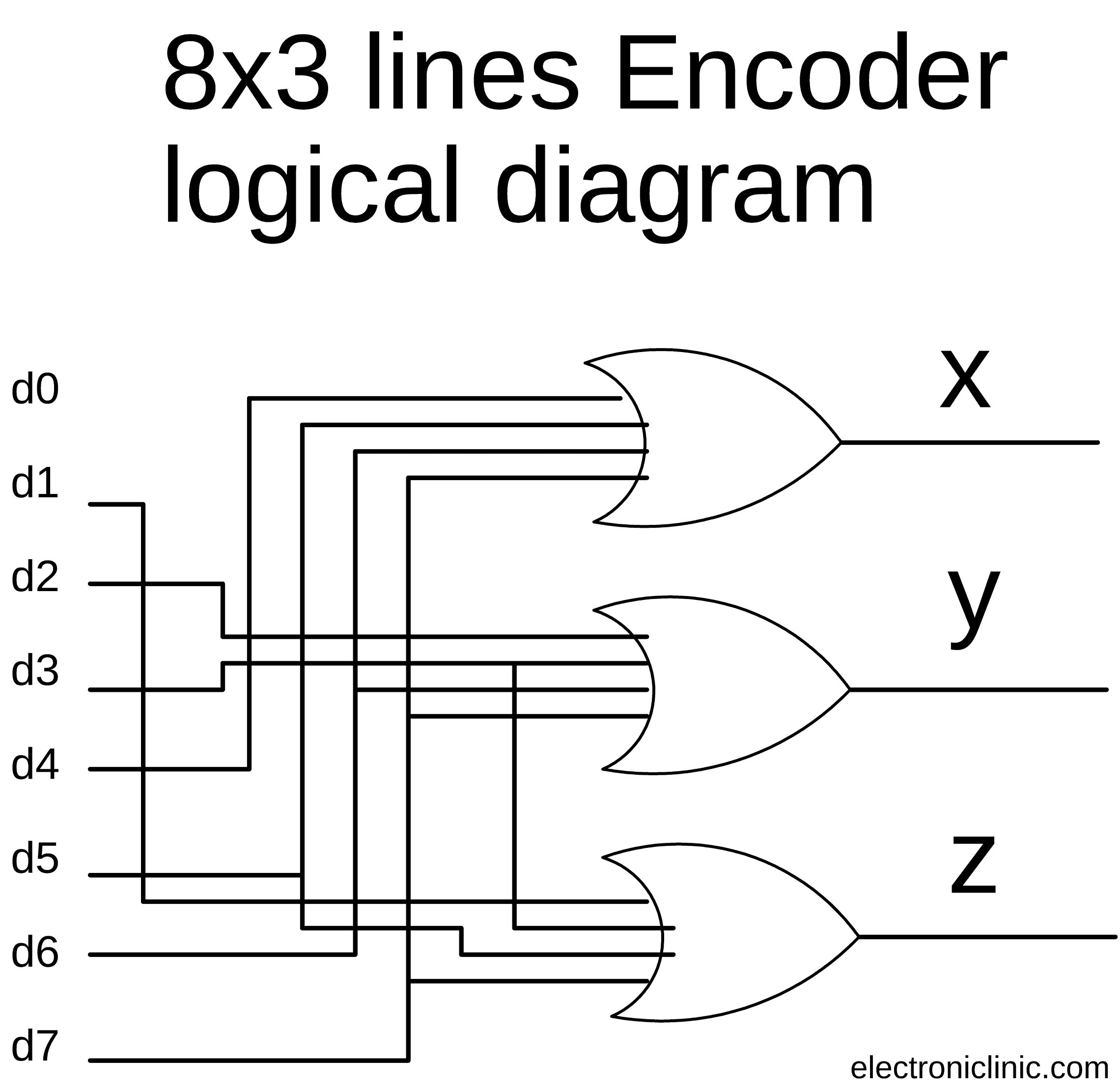
Web an encoder is a combinational circuit that performs reverse function of a decoder. An encoder is a device that converts the active data signal into a coded message format or it is a device that converts analogue signal to digital signals. 8 to 3 line encoder:
It Accepts 2 N Input And Produces Output In N Output Lines.
Asked jul 9, 2020 in computer by abha01 (51.9k points) icse; Web the logical expression of the term a0 and a1 is as follows: Web logic diagrams have several applications in investigations, and are most often developed in an iterative fashion.
With Our Easy To Use Simulator Interface, You Will Be Building Circuits In No Time.
Web encoder | combinational logic circuits | electronics tutorial home > combinational logic circuits > encoders prev next encoder encoder is a kind of multiplexer having. Web explore digital circuits online with circuitverse. Web name the logic gate for the following circuit diagram and write its truth table.
Web In This Video, The Binary Encoder Circuit Is Explained In Detail.
Web a general encoder's block diagram. Web google classroom computers often chain logic gates together, by taking the output from one gate and using it as the input to another gate. As shown in the event tree logic diagram in figure 31.4, in the.
That Is, If There Are 2 N Input Lines, And At Most Only One.
Web the circuit diagram of 4 to 2 priority encoder is shown in the following figure.

Pin on Electronic Circuit Diagrams

Encoder Logic Diagram And Truth Table / Logic Diagram And Truth Table

What is the circuit's logic diagram of a (2bit binary to decimal

4 To 2 Encoder Circuit Diagram

Pin on Digital Electronics circuits

Encoder Logic Diagram And Truth Table / Logic Diagram And Truth Table
Encoder Digital Logic Nancy Circuit

Design a 4 Input Priority Encoder by Using Wagner Criess
