Lock Circuit Diagram
Web the wiring diagram will show us how to construct the circuit that powers the electromagnetic door lock. Web to help you out, we put together this guide on elock magnetic lock wiring diagrams. Web the circuit diagram for raspberry pi solenoid door lock is very simple as you only need to connect the solenoid door lock to raspberry pi. Web an electronic bicycle lock circuit diagram gives us a look into the world of digital security.
555 Timer Based Simple Electronic Code Lock Circuit
By studying the circuit diagram, we can see how these locks use a combination of. Pin 1 is the input pin. Web (a) power supply circuit diagram and (b) magnetic door lock circuit.
Each Rfid Card Has A Unique Id Embedded In It And.
12v fan on 230v circuit. Web if we connect the solenoid lock to a relay (normally open mode): Web a properly drawn electric door lock wiring diagram should include all the necessary components, wires, and connections.
When Relay Is Open, Door Is Unlocked.
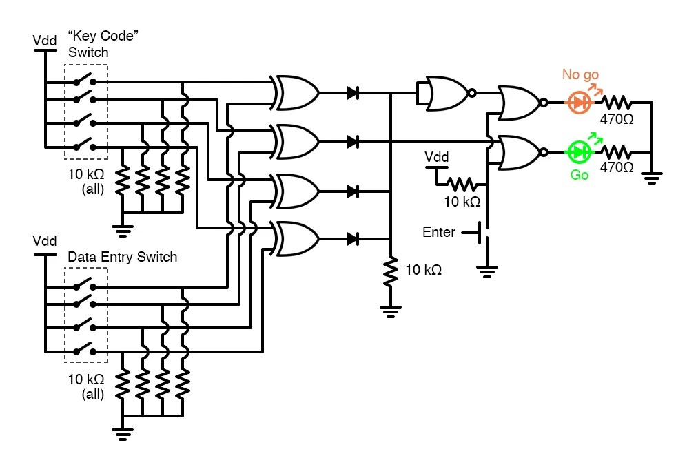
To use the lm7805 as a voltage regulator, two capacitors are connected across the input and the output pin. Web i am trying to figure out how to create a combination lock using logic gates, so that a password must be input (let's say pressing numbered buttons) in the correct. When relay is closed, door is locked.
I.e., When The Pll Is In Lock, The Vco Frequency Is Identical To The Signal Input, Except For.
It should also indicate any additional. Connect the input pin of the ic to the. By connecting arduino to the relay, we.
12V To 24V Dc Converter Power Supply Circuit Diagram.
It will include two wires, one for the power source and one for. Web this 7805 ic circuit diagram designed to give fixed 5v dc at output, you can choose different voltage rating ic (78xx) and corresponding input power source to get desired. When installing the elock magnetic lock, you will need to connect power to the circuit.
Web Lm7805 Pinout Diagram :
Rfid stands for radio frequency identification.

door lock circuit Page 3 Security Circuits Next.gr
Logic Circuit Diagram Of 1 To 8 Simple Combination Lock Digital

Keypad Door Lock using AVR Microcontroller Atmega16 Circuit Diagram

Electronic Combination Lock with Auto Reset Circuit Diagram

RFID Security Lock Circuit using Arduino

Door Lock Circuit using Digital Code

Password lock circuit diagram

555 Timer Based Simple Electronic Code Lock Circuit
